FM 16 CAVITATION DEMONSTRATION UNIT
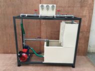
DESCRIPTIONOne of the most common causes of cavitation effects are fast moving objects in the water, such as the impellers of a centrifugal pump. If cavitation occurs on the impeller, the high mechanical stress sometimes results in separation or deformation of particles from the surface. In addition to the impeller geometry, intake pressure and temperature are also relevant for the occurrence of cavitation. The unit can be used to demonstrate cavitation effects on impellers of centrifugal pumps. Pump housing and the pipe at the inlet side of the pump are made of transparent plastic in order to visualize the cavitation processes. It is possible to capture excellent images of the vapour bubbles by taking photographs with short exposure times (flash). In order to influence the flow velocity at the impeller blades, the speed can be changed within a wide range via a frequency converter. Valves at the inlet and outlet of the pump enable the flow rate and pressures to be adjusted accordingly.
- • visualisation of cavitation effects in a transparent pump
- • continuously adjustable pump speed
- • closed water circuit
- • formation of cavitation
- • observation of cavitation effect
- • how speed, inlet pressure, flow rate and temperature affect cavitation
TECHNICAL SPECIFICATIONS
| Centrifugal pump with drive motor | power consumption: 0,37kW speed: 660-2800 RPM Max. flow rate: 100L/min Max. head: 6m |
| Tank | 20L |
| Measuring ranges | pressure (inlet): -1…0bar • pressure (outlet): 0…1,5bar • temperature: 0…100°C • flow rate: 150 LPM Rotameter • 230V, 50Hz, 1 phase |
| Dimensions | LxWxH: 1000x630x590mm, Weight: approx. 65kg |
| Required for operation | water connection: approx. 100L/h drain |
| Scope of delivery | 1 experimental unit 1 set of hoses 1 set of instructional material |
The whole setup is well designed and arranged in a good quality painted structure.
Weather
