FM-HBA-19 KAPLAN TURBINE (HYDRAULIC BENCH ACCESSORIES)
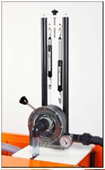
DESCRIPTIONThis demonstration turbine provides a simple low cost introduction to the Kaplan (axial flow) turbine showing its construction, operation and performance. A tapering, spiral shaped volute conveys water to the runner via a ring of guide vanes that are adjustable in angle to vary the flow through the turbine. Water enters the runner tangentially at the periphery, flows axially outward through the blades towards the hub then exits axially via a draft tube. Power generated by the turbine is absorbed by a Prony friction brake consisting of a pair of spring balances attached to a brake belt that is wrapped around a pulley wheel driven by the runner. The load on the turbine is varied by tensioning both spring balances which increases the friction on the pulley wheel. Brake force is determined from the difference in the readings on the two spring balances and the torque calculated from the product of this force and the pulley radius. The head of water entering the turbine is indicated on a Bourdon gauge and the speed of rotation is measured using a non-contacting tachometer (not supplied).The volute of the Kaplan turbine incorporates a transparent front cover for clear visualisation of the runner and guide vanes.
- Determining the operating characteristics, i.e. power, efficiency and torque, of a Francis Turbine at various speeds and guide vane opening
- Hydraulic Bench
- Water Supply & Drain
- Electricity 1 kW, 220V AC, Single Phase
- Floor Area 1.5 x 1.5 m
TECHNICAL SPECIFICATIONS
| Product | KAPLAN TURBINE |
|---|---|
| Product Code | FM-HBA-19 |
| Speed range | 0 to 1000 r.p.m |
| Diameter of Francis runner | 60 mm |
| Number of blades on runner | 12 |
| Number of guide vanes | 6, adjustable from fully open to fully closed |
| Range of spring balances | 0 to 10 N x 0.1 N |
| Range of Bourdon gauge | 0 to 2 bar |
The whole setup is well designed and arranged in a good quality painted structure.
Weather
