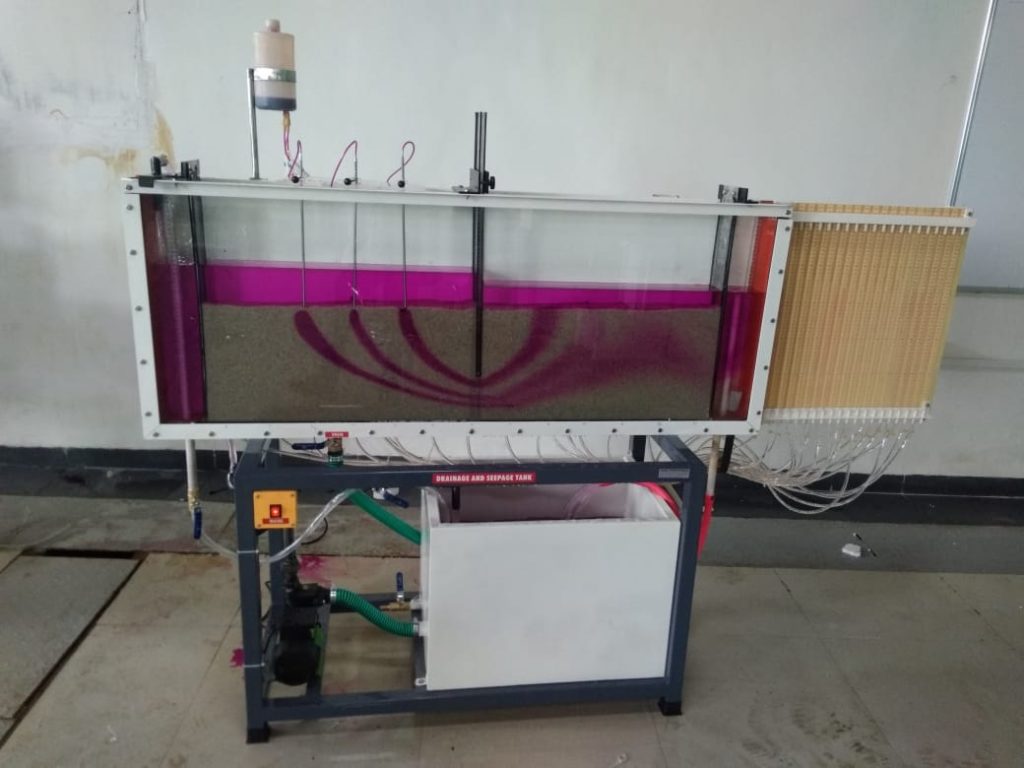
The bed of the tank is made from painted mild steel. The sides of the tank are supported and sealed by a well proven method which allows free access to the interior and results in minimum sight obstruction. One side is of toughened glass to give good scratch free visibility over a long period of use while the other is made of aluminium which permits the insertion of pressure tapping points as required. The ends of the tank are made of steel plate.
Adjustable overflows are provided close to each end of the tank so that constant water levels may be maintained in each half of the tank. These may be lowered to a position close to the bed of the tank for some experiments to provide subsoil drainage. The equipment is self-contained, requiring only an initial fill with cold water and connection to the electricity supply. The sump tank can be emptied to a laboratory drain.
TYPICAL STUDENT EXPERIMENTS INCLUDE
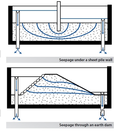
Seepage underneath a sheet pile wall
Seepage through an earth dam
Control of seepage through permeable soils by sub-soil drainage
Distribution of uplift pressure on hydraulic structures
Reducing uplift pressure and lateral thrust by drainage
Formation and behaviour of ‘Quicksand’
Stability of an earth dam
Draining an excavation site using wells
EXPERIMENTAL CAPABILITIES
Flow line visualization
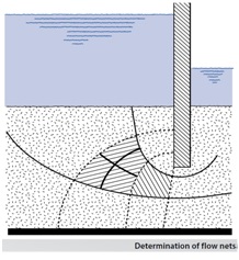
Flow net construction
Determining Seepage rates
Verification of Darcy’s law
Comparison of experimental results with analytical solutions
determining flow nets in permeable media graphically
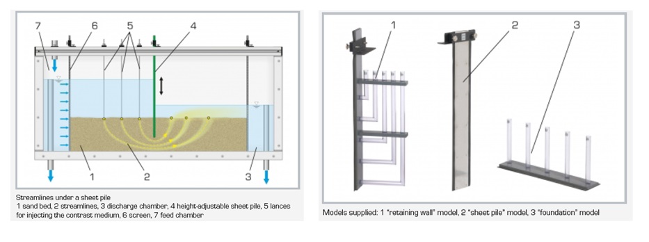
streamlines under a sheet pile
streamlines through an earth dam
drainage at an open ditch
determining the pressure curve at a foundation
determining the pressure curve at a retaining wall
groundwater levels over time in various Models
SPECIFICATIONS
A self-contained facility for study of flow through permeable media
The tank has a toughened glass front and aluminium back to permit the insertion of pressure tappings as required.
Six tapping points are provided
The design of the side supports allows free access to the interior with minimum sight obstruction
Supply includes sump tank, pump, starter and control valve. Also a dye injection system and a selection of models
Comprehensive instruction manual with data sheets and student experiments
Working section 1500mm x 100mm x 600mm
BASIC ACCESSORIES
Foundation pressure plate
Straight permeable membrane
Curved permeable membrane
Lateral pressure plate
Tile drain
UTILITIES REQUIRED
Electricity supply: 220-240V/1ph/50Hz, 1A
Sand (1…2mm grain size)
TECHNICAL DETAILS
Product & code
Drainage and seepage tank & Ahh – 02
Experimental section
Tank made up of SS304 with one side toughened glass of 6-8 mm thickness
Size: LxWxH: 1500 x 102 x 625mm
Inclination of base of the tank
The inclination of base of the tank with respect to ground surface adjustable up to angle range of 00 -150.
No of piezometers
13 nos on bottom and 6 no.s on back with 650 mm water manometer
Dye Injection system
Dye Injection system with 0.5 ltr capacity & three probes.
Pump
Max. flow rate: 4m3/h and Max. head: 4m
Sump Tank
MOC SS 304, Capacity 100 ltrs
Adjustable Overflows
Adjustable overflows provided close to each end of the tank so that constant water levels may be maintained.
Well Outlet
2-3 nos of well outlet provided at the base of the tank to represent leakage layer at the base.