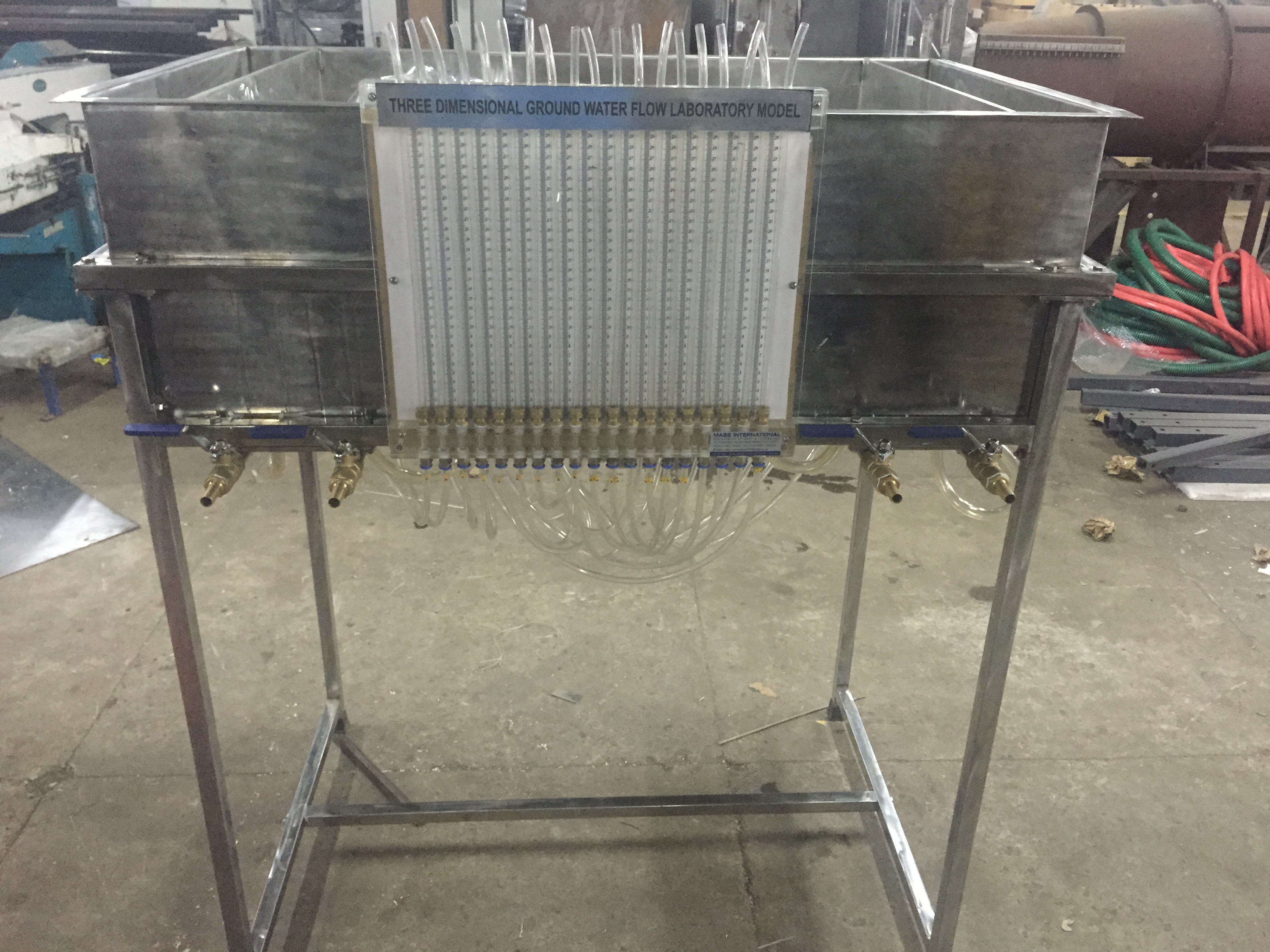
This bench-mounting apparatus is capable of demonstrating, on a small scale, the hydrological principles of ground water flow with capability of following demonstration.
Ground Water Flow Unit allows simple three dimensional flow situations to be set up quickly and measurements of piezometric levels taken at appropriate positions within the model.
The sand tank is manufactured in SS for durability in service and is located in a painted mild steel frame which is designed for standing on a laboratory bench.
A diffused water inlet/outlet with associated flow control valve is installed at each end of the sand tank. This facility allows the desired water table to be established for the various demonstrations of groundwater flow.
Two wells with control taps in the base of the tank allow studies of abstraction.
Groundwater Flow Demonstration Unit Nineteen tappings in the base of the tank arranged in a cruciform configuration are connected to a multi-tube piezometer on the side of the tank. These indicate the profile of the water table in the sand.
TECHNICAL DETAILS
Tank: – Length: 1.0 m
Width: 0.6m
Depth: 0.3 m
Piezometer: – Range: 0 to 300mm (19 no.)
Calibrated: 1mm internvals
DEMONSTRATION CAPABILITIES
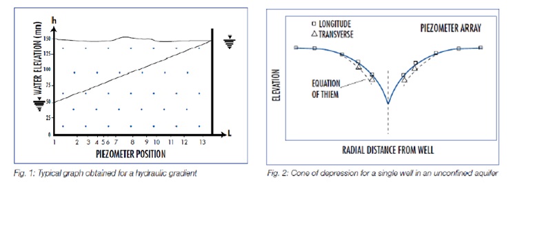
Hydraulic gradient (Darcy’s Law) resulting from groundwater flow between two potentials can be demonstrated visually. Levels in the piezometer tubes are plotted to show a linear profile (fig.1).
Water flowing into a well creates a depression in the water table. The contour of the water table is plotted using the levels in the Piezometer tubes. Results obtained can be compared with Depuit’s or Thiem’s formulae (fig.2).
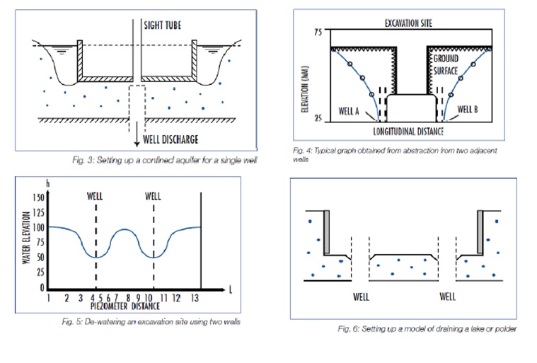
Fig.3 shows the construction of a single well in a confined aquifer with radial symmetry.
A profile of the water table can be obtained (fig.4) when using two wells simultaneously. It is possible to compare the result with theoretical results obtained for a single well using the method of superposition.
A rectangular ring is used to form the sides of an excavation below the level of the water table.
Wells are used to lower the water table in the vicinity of the excavation. Thus the excavation is prevented from filling with water (fig.5).
A large rectangular ring is used to create a polder or lake. Water flowing into a ditch near the wall is drained via the two wells. The experiment differs from the de-watering of a site as drainage takes place from the floor of the polder. Fig.6 shows the construction.