Skip to content
FM 02 B
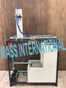
VENTURIMETER & ORIFICEMETER APPARATUS
Description
The apparatus consists of two pipelines emerging out from a common manifold. One pipeline contains a Venturimeter and other contains an Orifice. The pressure tapings from the Venturimeter and Orificemeter are taken to differential manometer to measure pressure difference. The Venturimeter & Orificemeter are connected in parallel and anyone of them can be put in operation by operating valves provided at the downstream. These valves can also regulate the flow.
Present set-up is self-contained water re-circulating unit, provided with a sump tank and a centrifugal pump. Flow control valve and by-pass valve are fitted in water line to conduct the experiment on different flow rates. Flow rate of water is measured with the help of measuring tank and stopwatch.
EXPERIMENTS
- To determine the co-efficient of discharged through Venturimeter and orifice meter.
- To measure discharge through Venturimeter and Orificemeter as flow meters.
FEATURES
- Acrylic test section
- Closed loop water circulation
- Compact & stand alone set up
- Stainless Steel tanks
- Superb Painted structure
- Simple to operate & maintain
UTILITIES REQUIRED
- Electric supply5 kW, 220V AC, Single Phase
- Water supply Tap water connection ½” BSP Distilled water @ 60 liters (optional)
- Floor Area with Drain facility
TECHNICAL DETAILS
| Product & Code |
Venturimeter & Orificemeter Apparatus and FM 02 B |
| Venturimeter |
Material Clear Acrylic compatible to 1″Dia. Pipe |
| Orificemeter |
Material Clear Acrylic/ Brass/SS Plate compatible to 1″ Dia. Pipe. |
| Water Circulation |
FHP capacity make Crompton Greaves / Kirloskar |
| Flow Measurement |
Capacity 30 Ltrs. MOC SS fitted with Piezometer Tube & scale |
| Sump Tank |
Capacity 50 Ltrs MOC SS |
| Piping |
MOC GI and PVC |
| Stop Watch |
Electronic |
| Control Panel |
On/Off Switch, Mains Indicator, etc |
| Overall Dimensions |
(L x B x H) 120 x 42 x 120 cm |
error: Content is protected !!