FM 13 STUDY OF PRESSURE MEASUREMENT
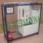
DESCRIPTIONThe set-up consists of different pressure measurement devices fitted in a pipe line, in which an Orifice is fitted to create the pressure difference. The student scan has good insight-of the devices. Present set-up is self-contained water re-circulating unit, provided with a sump tank and a centrifugal pump etc. Flow control valve and by-pass valve are fitted in water line to conduct the experiment on different flow rates. Flow rate of water is measured with the help of measuring tank and stop watch.
RANGE OF EXPERIMENTS
- • To demonstrate the working of different pressure measuring devices
- • To measure the pressure practically by different pressure measuring devices
FEATURES
- • Choice of Test Section
- • Closed loop water circulation
- • Compact & stand alone set up
- • Stainless Steel tanks and wetted parts
- • Superb Painted structure
- • Simple to operate & maintain
UTILITIES REQUIRED
- • Electric supply 0.5 kW, 220V AC, Single Phase
- • Water supply Tap water connection ½” BSP Distilled water @ 60 liters (optional)
- • Floor Area with Drain facility
TECHNICAL SPECIFICATIONS
| Product & Code | PRESSURE MEASUREMENT APPARATUS & FM 13 |
|---|---|
| Test Section | Pipe Dia 1” Orifice dia ½” Single Well Manometer Single Tube Type Differential Manometer U Tube Type Sensitive Manometer Inclined Tube Type Pressure Gauge. Bourdon Type Vacuum Gauge Bourdon Type |
| Supply Tank | Capacity 50 MOC SS |
| Measuring tank | Capacity 30 Liters MOC SS fitted with Piezometer Tube & scale |
| Pump | FHP capacity make Crompton Greaves / Kirloskar |
| Piping | MOC GI and PVC |
| Stop Watch | Electronic |
| Overall Dimensions | (L x B x H) 120 x 42 x 190 cm |
The whole setup is well designed and arranged in a good quality painted structure.
Weather
