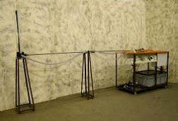
FM 19 PIPE SURGE AND WATER HAMMER
DESCRIPTIONPipe surge & water hammer are two related but independent phenomena which arise when fluid flowing in a pipe is accelerated or decelerated. The associated pressure transients can be damaging to pipe work or components and systems must be designed to avoid or withstand them. The equipment designed clearly demonstrates the different effects resulting from gradual or instantaneous changes in fluid velocity (created by slow and fast valve closure). Effect of initial fluid velocity can also be investigated. Pipe surge resulting from a gradual change in fluid velocity is clearly seen as fluctuating changes in head in a surge shaft. Water hammer resulting from a rapid change in fluid velocity is clearly seen as large changes in pressure monitored using a pair of transducers and indicated using an oscilloscope. The equipment comprises two SS pipes connected to a constant head tank. A service module provides the water supply to the head tank and also incorporates a volumetric tank for flow rate measurement, sump tank, circulating pump and flow control valve. Water enters the two test pipes via the constant head tank and discharges into the volumetric tank. A dump valve in the volumetric tank returns the water to the sump tank. The pipe surge test section incorporates a clear acrylic surge shaft to enable visualisation of its oscillatory characteristics to be demonstrated. A metric scale on the shaft permits the height of the oscillations to be measured. The test pipe terminates with a lever operated gate valve and separate flow control valve. The water hammer test section uses a unique fast acting valve specifically designed. Pressure transducers mounted at the fast acting valve itself and at a point along the test pipe provide analogue outputs which are fed into a signal conditioning module. The corresponding output voltage from the signal conditioning module can then be fed into a dual trace oscilloscope. Output is available from the oscilloscope. This allows the stored display to be transferred onto a suitable printer to provide a hard copy of the transient.
- • Demonstration of pipe surge
- • Determination of oscillatory characteristics of the surge shaft
- • Demonstration of frictional head loss between reservoir and surge shaft
- • Comparison between theoretical and measured pressure profiles produced by water hammer
- • Using a dual trace storage oscilloscope to record transient water hammer pressure profiles
- • Measuring the pressure profile characteristics
- • Determination of the velocity of sound through a fluid in a pipe
- • Demonstration of the effects of cavitations on subsequent cycles.
- • Clear test section for visualization of phenomena.
- • Superb Painted structure
- • Simple to operate & maintain
 UTILITIES REQUIRED
- • Electric Supply: 220/240V/1ph/50 Hz @10 A
- • Water Supply: 300L/h, drain
- • Floor Area: 4.0 x 1.0 x 2.0 m
TECHNICAL SPECIFICATIONS
| Product & Code | Pipe Surge and Water Hammer & FM 19 |
|---|---|
| Pipe Surge test pipe | SS 22mm I/D x 3m long clear acrylic |
| Surge Shaft | Clear acrylic 40mm I/D x 800mm H |
| Head Tank | Cap. 45 ltr made from SS |
| Water hammer test pipe | SS 22mm I/D X 3m long |
| Pressure Transducer | 2 off range, 1 to 15 bar |
| Oscilloscope | Dual trace storage oscilloscope |
The whole setup is well designed and arranged in a good quality painted structure.
ABOUT OUR COMPANY
WE MANUFACTURERS WIDE RANGE OF PRODUCTS LIKE HEAT TRANSFER LAB EQUIPMENT, HYDRAULIC BENCH, HYDRAULIC MACHINES LAB EQUIPMENT, ETC. WE MANUFACTURE THESE PRODUCTS AS PER THE LATEST MARKET TRENDS AND DELIVER THESE AT USERS’ PREMISES WITHIN THE SCHEDULED TIME FRAME.
Contact Us
Have questions, comments or just want to say hello:
- mass_international99@yahoo.co.in
- 92156-00789 , 9215900789, 9812225689, 9812200689
- Regd. Office Works:
Plot No. 459, Sector – 2, Phase – 1, Industrial Estate Growth Centre,HSIIDC, Saha – 133104
GSTIN. No. 06ADYPK5042P1ZS
Website Design By | Design: Fame Digital Worlds by Fame Digital Worlds
