| Product & Code |
sub sonic Wind tunnel HM 18S |
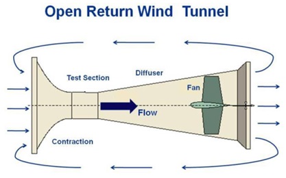
| Type of Wind Tunnel |
Open Type Wind Tunnel Low speed, open circuit, suction type
Approx velocity 25 to 30 m/sec |
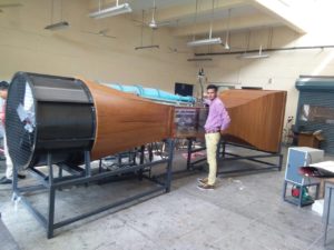
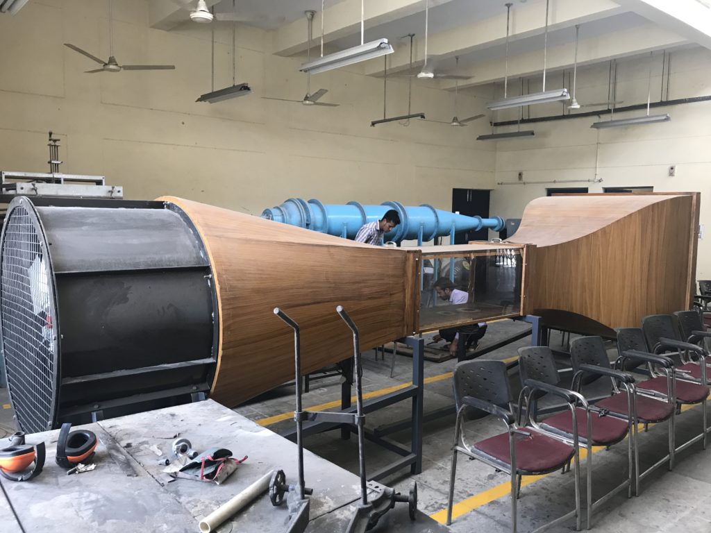
| Wind Tunnel
Construction details MOC & Size |
Wood ( Hunsur – Mysore /Ghana teak)
Plywood: 710 grade 3 mm thick for curved section, 7-8 mm for straight sections
18mm plywood to be used for making test section
of contraction, transition, diffuser and,
Fan Duct Made of MS
Effuser: Made of wood (Hunsur-mysore/Ghana teak) with MS support
Diffuser: Square to round section of 600 mm Diameter made of Contraction ratio CR of body with MS support
Total Length 7.50 to 8.00 m
Contraction ratio: 9:1
Honey comb: 8:1 |
| Test Section |
300x 300 x 600mm (length) with acrylic windows on either side of the test section.
Top opening and provision to place the traverse / pitot static tube along the length of the test section.
Provision for lighting the test section.
A turn table at the bottom of the test section for mounting models. |
| Fan Unit |
Axial flow with rigid MS support / frame
Motor of Capacity 2.2 KW, 1450 RPM with Variable Speed AC Drive
Ac Motor Controller/ Drive
– Variable frequency drive.
– High performance V/F control with both closed & open loop control .
– Digital display RPM. Voltage & current , power O/P in KVA and KW
– touch keypad for varying motor RPM, Start & Stop, |
| Wind Tunnel Accessories |
|
Air Velocity Measurement |
Pitot Static Tube: Prandyl type
Static Tube: Prandyl type
Total Pressure Tube: Prandyl type
By pitot tube 24 to 28 m/s length 350 mm, Tube Diameter ¼”
With Digital pressure indicator & U tube manometer |
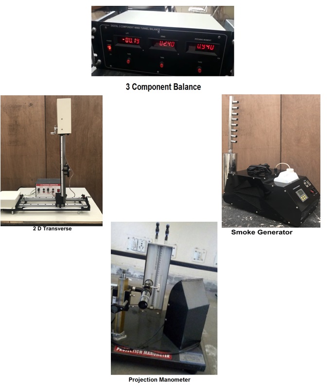
| 2 Component Balance |
Lift force and drag force
Lift- 10 Kg.
Drag- 3 Kg
Strain gauge with amplifier with digital indicator |
| 2D Transverse Motorized |
X- Axis along the flow & Y-Axis perpendicular to the tunnel
Range: 350mm
Compact & uses linear movement block (LM Block) for rigidity of the movement and ball-screw nut for manual as well as motorized controlled movement of the LM block
Diameter of the screw 15mm, Pitch of the screw 5mm
Linear scale fixed to the support gives 1mm readings.
Circular disc fixed to the shaft of the screw gives has 100 divisions on the circumference. This gives a movement 0.05 mm / division.
A disc with a handle is provided for continuously rotating the screw for movement of the traverse when the movement is mechanical. |
| Symmetric & Cambered Aerofoil |
NACA-662015, 150mm chord length, 15% thick.
Symmetrical aerofoil model for lift-drag study
Symmetrical aerofoil model for pressure distribution study With 15 pressure ports |
| Multiple Tube Manometer |
15-20 x 400mm ht PVC Tubes 0-45° inclination with vertical axis with separate Stand for pressure distribution study |
| Smoke generator |
Smoke generator using liquid parofin and smoke rake to suit the above tunnel |
| Control Panel |
Consisting of
Digital lift drag indicator
Variable Speed AC Drive with digital speed indicator
Digital pressure indicator & U tube manometer of Pitot tube arrangement |
| Extra Accessories Optional Available |
| Cylinder |
50mm dia with 20 pressure ports |
| Wake Rake |
20 ports |
| Boundary Layer Rake |
15 ports with surface plate |
| Projection Manometer |
An instrument for measuring differential pressure, in the range of 0-300mm Water/Alcohol head. The above manometer is used for measurement of wind speeds in wind tunnel and ducts up to a speed range of 0 to nearly 30meter/sec.
The projection manometer can also be used for measurement of differential air pressure in the range of 0 psi to about 0.45 psi. The projection manometer is an accurate instrument, easy to use and rugged. The accuracy of this instrument is 0.1mm height of the liquid used. |