HM-21 HYDRAULIC FLOW DEMONSTRATOR


  • Demonstrate flow through both open channels and close conduits using this highly visual accessory to the Hydraulics Bench
  • Unique elevating bed section and models of various hydraulic structures allow the difficult concepts of critical flow and energy changes to be clearly demonstrated and analyzed
  • Working section large enough for the various flow phenomena to be seen clearly by a group of students
  • enables a teacher to provide practical demonstrations at the same time as explaining the theory
  • Demonstrations can be set up quickly and easily, including varying the upstream and downstream flow conditions
  • Ideal for student project work – user constructed models of different hydraulic structures can be evaluated


Description


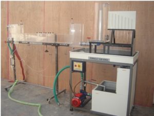
The flow channel of the Hydraulic Flow Demonstrator is constructed using clear acrylic for visibility and is supported by a floor-standing, metal frame fitted with castors for mobility.

The flow channel consists of an inlet tank with overflow and flow stilling arrangement, a rectangular working section and a discharge tank.

Control valves and adjustable weirs allow the flow conditions to be varied independently at the entry to and exit from the working section. The working section can be flooded to create a closed conduit or operate partially filled as an open channel.

The most important feature of this equipment is the adjustable section of the bed which, together with its transition section (ramps), may be raised and lowered using an external actuator while the water is still fl owing. This facility affords a striking demonstration of the significance of channel critical depth. It is also used to vary the cross section for demonstration of the Bernoulli equation in closed conduit flow.

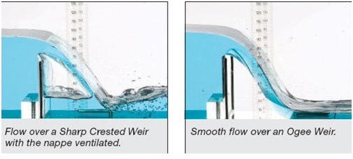
A removable panel in the roof of the working section allows models of typical hydraulic structures to be installed, namely; a Sharp crested weir, Broad crested weir (also used to create a Culvert) and Ogee weir.

Pitot tubes and tapings connected to a multi tube manometer allow Total and Static heads to be measured and compared at three locations in the working section. The height of the Pitot tubes is adjustable allowing the velocity profile to be determined at any position between the bed and the roof of the working section. Transparent scales allow all important heights and levels to be measured throughout the working section.

The Hydraulic Flow Demonstrator is designed to be used in conjunction with Hydraulics Bench, which provides a re-circulating water supply and a volumetric measuring facility.

The Flow Demonstrator can be used with an independent water supply of up to 1.6 litres/sec provided that water discharging from the channel can be intercepted.

An optional direct reading flow meter is available that allows rapid adjustment to the required flow conditions.


INSTRUCTIONAL CAPABILITIES


The Hydraulic Flow Demonstrator simply connects to a standard Hydraulics Bench to permit the study of the following basic aspects of fluid flow:


Closed conduit flow


  • Application of the Bernoulli and Continuity equations to converging and diverging flow
  • Effect of gradual and sudden changes in cross section (energy losses)
  • Using a contraction as a flow measuring device
  • Using a Pitot tube to measure velocity / velocity profile
  • Flow through a Culvert


Open channel flow


  • Flow beneath an Undershot Weir (Sluice Gate)
  • Flow over Sharp Crested, Broad Crested and Ogee Weirs
  • Using hydraulic structures to measure flow in an open channel
  • Effect of changes in upstream and downstream water level
  • Characteristics of Clinging, Aerated, Depressed and Drowned Nappes
  • Sub-critical, Critical and Supercritical flow/ depth. Changes in Specific Energy and control imposed by the minimum energy condition
  • Characteristics of Hydraulic Jumps
  • Force and energy conditions in a
  • Hydraulic Jump
  • Flow patterns associated with Hydraulic Jumps
  • Flow over Drop Structures / Energy Dissipation
  • Changes in flow profile in relation to the Froude Number (predicting flow conditions in an open channel)
  • Observation of flow patterns associated with flow around hydraulic structures
  • Velocity of gravity waves in shallow water / Formation of surface waves near critical depth
  • Project work – Evaluation of user constructed hydraulic structures


Utilities required


  • Hydraulic Bench


Technical details


Product & Code Hydraulic flow demonstration & HM-21
Width of working section 77mm
Depth of working section 150mm
Length of working section 1100mm
Maximum operating flow rate 1.6 litres/sec
Overall Dimensions (Approx.)


Length 2.20m

Width 0.63m

Height 1.60m

Weight (dry) 100kg

Weight and Volume (Approx.) Gross weight 250kg

Volume 3.4m3

error: Content is protected !!