Skip to content
HT 01
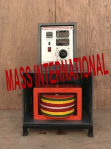
HEAT TRANSFER THROUGH COMPOSITE WALLS
EXPERIMENTS
- To determine total thermal resistance and thermal conductivity of composite wall
- To plot temperature gradient along composite wall structure
FEATURES
- Superb Painted structure
- Simple to operate & maintain
UTILITIES REQUIRED
- Electricity Supply: 1 Phase, 220 V AC, 2 Amp.
- Table / Floor Space for set-up support.
TECHNICAL SPECIFICATIONS
| Product & Code |
Heat Transfer Through Composite Wall & HT 01 |
| Slab Assembly |
Arranged symmetrically on both sides of heater
Slab Material: Slab Size
Cast Iron: 300 mm dia. & 20 mm thick
Bakelite: 300 mm dia. & 15 mm thick
Press Wood : 300 mm dia. & 12mm thick
Heater: Nichrome wire
|
| Temperature Sensors |
RTD PT-100type (8 Nos.)
|
| Control panel |
Digital Voltmeter : 0-300 Vol.
Digital Ammeter.: 0-2 Amp
Variac :0-230V, 2A
Digital Temperature Indicator: 0-200° C, with multi-channel switch, On/off switch, Mains Indicator etc
|
| Cabinet to accommodate the slab assembly, with front window of glass/acrylic |
|
| Overall Dimensions |
(L X B x H) 72 x 45 x 110 |
Painted rigid MS structure is provided to support all parts.
error: Content is protected !!