Skip to content
HT 09
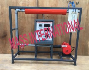
HEAT TRANSFER IN FORCED CONVECTION
Description
The apparatus consists of Blower unit fitted with the test pipe. Nichrome wire heater surrounds the test section. Four Temperature Sensors are embedded on the test section, two placed in the air stream at the entrance and exit of the test section to measure the inlet and outlet air temperature. Test pipe is connected to the delivery side of the blower along with the Orifice to measure flow of air through the pipe. Constant heat flux is given to pipe by an electric heater through a variac and measured by Digital Voltmeter and Digital Ammeter.
EXPERIMENTS
- To determine average surface heat transfer coefficient for a pipe losing heat by forced convection.
- Comparison of heat transfer coefficient for different airflow rates and heat flow rates.
- To plot surface temperature distribution along the length of pipe
FEATURES
- Superb Painted structure
- Simple to operate & maintain
UTILITIES REQUIRED
- Electricity Supply: 1 ϕ, 220 VAC, 10Amp.
- Floor area of 1.2mx 0.5m
| Product & Code |
Heat Transfer In Forced Convection & HT 09 |
| Test section |
Dia : 28 mm (approx.)
Length : 400 mm (approx.)
Blower : FHP of Standard make |
| Heater |
Nichrome Wire |
| Air Flow measurement |
Orificemeter & Manometer |
| Temperature Sensors |
RTDPT-100 type(6 Nos.) |
| Control panel |
Digital Voltmeter : 0-300Volt,
Digital Ammeter: 0-2Amp,
Variac : 0-230 V, 2 A, Digital Temperature Indicator: 0-3000C, with multi-channel switch,
On off switch, Mains Indicator etc. |
| Overall Dimensions |
(L x B x H) 100 x 40 x 90 |
|
Painted rigid MS structure is provided to support all parts
|
error: Content is protected !!