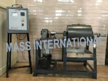
MO 11 BALL MILL
DESCRIPTIONBall Mills arc horizontal rotating cylindrical steel chamber of half filled with steel balls. The size reduction b accomplished by the impact of balls as they fall back after being lifted by the baffles fitted in the rotating chamber. Ball Mill is fitted on a sturdy MS frame. Charging of balls and material is done by the means of opening provided in the chamber. The chamber is turning about the horizontal axis through a reduction gearbox and a motor. An arrangement is done for moving the Ball Mill at different speeds. A revolution counter is provided to find out the number of turns. Special arrangement is done to free the Ball Mill from reduction gearbox for charging and discharging the material.
- • To study effect of rpm on the power consumption of a Ball Mill
- • To determine the efficiency of a Ball Mill for grinding a material of known Wi
- • To find the critical speed practically and theoretically and to study the effect of speed on efficiency
- • Feed Product
- • Electricity: 1 kW, 220 Volts AC, 1Ø
- • Floor area 1.5 x 1m
- • Set of sieves with sieve shaker for analysis
TECHNICAL SPECIFICATIONS
| Product & Code | BALL MILL & MO 11 |
|---|---|
| Jaw | Material MS Dia 275mm, Length 350mm. Thickness 5 mm |
| Discharge | Suitable size. |
| Feed Size | 6mm Approx. |
| Product Size | 200 Mesh (Approx.) |
| Drive | 1 H.P. Standard make DC Motor controlled by DC Drive, coupled to 2" Reduction Gearbox gives variable speed with Digital RPM Indicator, Non Contact type with Proximity sensor |
| Revolution Counter | Mechanical type, Standard make |
| Product Receiver | Material SS of suitable size |
| Control Panel | On/off switches, mains indicator etc |
The set-up is fitted with required guards
The whole set-up is well designed and arranged in a good quality painted structure.
Weather
