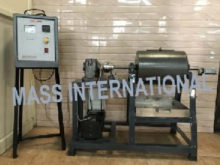
MO 13 ROD MILL
DESCRIPTIONRod Mills are horizontal rotating cylindrical steel chamber of half filled with steel rods of length slightly less than the length of chamber. The rods are of different diameter. The size reduction is accomplished by the impact of rods as they fall back after being lifted by the rotating chamber. Rod Mill is fitted on a sturdy MS frame. Charging of rods and material is done by the means of opening provided in the chamber. The chamber is turning about the horizontal axis through a reduction gearbox drive through a 1 HP motor. The stepped pulley arrangement is done for moving the Rod Mill at three different speeds. A revolution counter is provided to find out the number of turns. Special arrangement is done to free the Rod Mill from reduction gearbox for charging and discharging the material.
- • To study effect of RPM on the power consumption of a Rod Mill
- • To determine the efficiency of a Rod Mill for grinding a material of known Wi
TECHNICAL SPECIFICATIONS
| Product & Code | Rod Mill & MO 13 |
|---|---|
| Rod Mill (Chamber) | Material MS, Dia 275mm, Length 350mm. Thickness 5 mm |
| Discharge Chute | Suitable size |
| Drive | 1 H.P. Crompton Make motor coupled to 2" Reduction Gearbox & 3 step pulley to get 40, 50 and 60 RPM |
| Revolution Counter | Mechanical type, Standard-make |
| Product Receiver | Material SS of suitable size |
| Control Panel | Energy measurement: Energy meter Standard make. Starter: 1 HP, Single Phase, Standard Make. MCB: For overload protection. Voltmeter: Analog type, 0-300 V, Standard make. On/off switches, mains indicator etc. |
The set-up is fitted with required guards.
The whole set-up is well designed and arranged in a good quality painted structure.
Weather
